ArchiMate® provides an architecture description language which defines core concepts of an EA model as well as their graphical illustration. The core of ArchiMate® is the ArchiMate® framework, which allows to categorize elements along two dimensions [16].
ArchiMate® Foundations
ArchiMate® is an Open Group standard maintained by the Open Group ArchiMate Forum. Successive versions are published at regular intervals, with the latest release being ArchiMate® 3.0 published mid 2016. It comprises an enterprise architecture modeling language specification as well as the ArchiMate® Framework [16].
In ArchiMate® a model is defined as being a “collection of concepts” and a concept as “either an element or a relationship”. The enterprise architecture modeling language specification provides a precise definition and illustration of the concepts specific to the domain of enterprise architecture. This modeling language can be used to represent enterprise architectures as well as to describe their changes over time [16].
The ArchiMate® Framework is depicted in Figure 1. It enables a categorization of the core entities defined by the ArchiMate® modeling language. The framework categorizes these core entities along two dimensions [16].
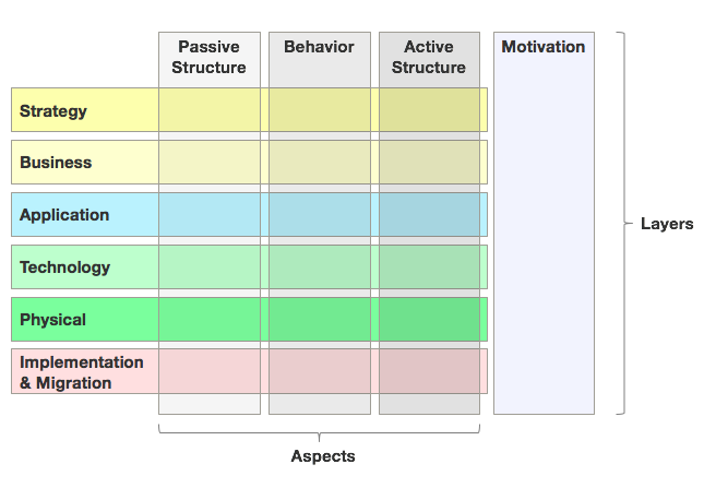
Figure 1: The ArchiMate® Framework as specified in the ArchiMate® 3.0 Specifications. [Source: ArchiMate® 3.0 Specification, an Open Group Standard. Standard. The Open Group, 2016.]
The first dimension core entities are assigned to are the different layers of an enterprise architecture model. In the new ArchiMate® Version 3.0, the enterprise architecture model is split into the Strategy (e.g. capability), the Business (e.g. business actor), the Application (e.g. application function), the Technology (e.g. artifact), the Physical (e.g. facility) and the Implementation & Migration (e.g. deliverable) layer. With regards to the graphical representation of single entities, the layer an entity belongs to is indicated using different colors [16].
The second dimension is made up of four aspects, which the core entities are allocated to. In the graphical representation of elements, the assignment of an element to an aspect is visualized using different shapes. The first aspect represents active structures, capturing subjects that display actual behavior (who?). These active structures are represented using boxes with square corners and an icon in the upper-right corner. The behavior aspects represent behaviors of active structures (how?) and are visualized using boxes with round corners and an icon in the upper-right corner. Passive structures are the objects behavior is performed on (what?). There is no global way to visualize them with regards to the shape. Finally, motivation constitutes the fourth aspect in the ArchiMate® Framework (why?). Elements assigned to this aspect are depicted using boxes with diagonal corners but are also color coded, indicating that it also constitutes a layer [16].
An excerpt of the language notation for elements of the ArchiMate® modelling language together with their definitions and an assignment to a layer and aspect is displayed in Figure 2 [16].
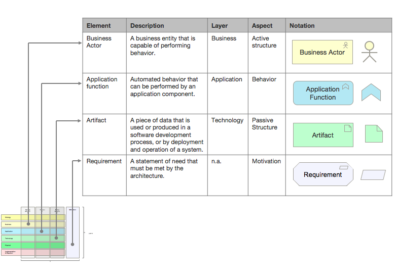
Figure 2: Excerpt of the language notation for elements of the ArchiMate® modelling language with their definitions, their assignment to layers and aspect and their assigned icons. [Based on: ArchiMate® 3.0 Specification, an Open Group Standard. Standard. The Open Group, 2016.]
Relationships between these elements can be categorized and visualized using a set of connector icons. General types of relationships defined in ArchiMate® are structural relationship, dependency relationships, dynamic relationships and other relationships. An excerpt of these types of relationships, their definitions and their icons is available in Figure 3 [16].
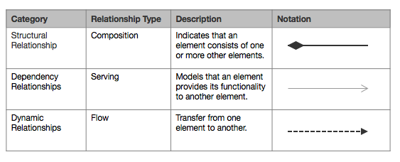
Figure 3: Excerpt of types of relationships in ArchiMate®, their definitions and their icons. [Based on: ArchiMate® 3.0 Specification, an Open Group Standard. Standard. The Open Group, 2016.]
Relation between ArchiMate® and TOGAF®
ArchiMate® is closely related to the TOGAF® standard and provides the modeling language that can be applied to the models created in TOGAF®. The ArchiMate® Framework can be mapped to the TOGAF ADM as illustrated in Figure 4 [16].
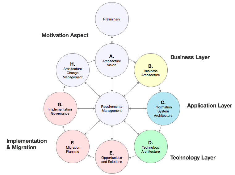
Figure 4: Mapping of the the ArchiMate® Framework to the TOGAF® ADM. [Based on: ArchiMate® 3.0 Specification, an Open Group Standard. Standard. The Open Group, 2016.]
Advantages & Disadvantages of ArchiMate®
One advantage of ArchiMate® is that it enables the visualization of architectures on separate layers but also allows the depiction of cross-layer relationships, as illustrated in the examples in Figure 5 [16].
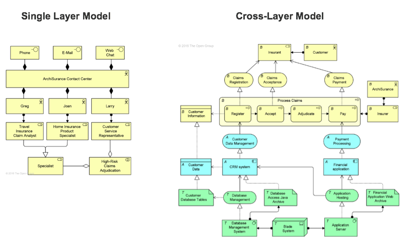
Figure 5: Examples of a single layer and a cross-layer enterprise architecture model. [Source: ArchiMate® 3.0 Specification, an Open Group Standard. Standard. The Open Group, 2016.]
Additionally, ArchiMate® provides extensive list of enterprise architecture entities, a predefined meta-model, some simplified standard views and publicly available, comprehensive documentation. Also, tool support for modeling the enterprise architecture using this architecture description language is available [BBL12].
A downside of ArchiMate® is that there is a limited extensibility of the modeling language. Further, some concepts are ambiguous [BBL12] and modelers need training to apply the framework successfully. Finally, when implementing ArchiMate®, a terminology mapping assigning existing concepts to the ArchiMate concept needs to be conducted.
| [16] |
ArchiMate® 3.0 Specification, an Open Group Standard. Standard. The Open Group, 2016. |
| [BBL12] |
S. Bente, U. Bombosch, and S. Langade. Collaborative Enterprise Architecture: Enriching EA with Lean, Agile, and Enterprise 2.0 Practices. Elsevier, Inc., 2012. |